POC: Get the status parameter from an EcoFlow power station

I own an EcoFlow RIVER 600 Pro with an 110 Watt solar panel. Since all the parameters of the station can be seen in the EcoFlow app there must be somehow a way to get it per script.
I found a thread regarding iobroker but this was related to a web api provided by EcoFlow. You need to write them to get an access token.
Fortunately I found a github repository for an integration with Home Assistant:
https://github.com/vwt12eh8/hassio-ecoflow.

It took me some time to adapt the source to work standalone. Please note that its just a poc. The repository can be found here: https://github.com/wsoltys/ecoflow-stats

In the current form it outputs just a dict of the values received.
Example output prettified:

Note: This is not an official API and further firmware updates can break the functionality.

Simple IPv4 and IPv6 HTTP Server

When doing hackthebox stuff I often use the SimpleHTTPServer module of python to download scripts and tools from my host system to the client.
Recently I needed an IPv6 http server because IPv4 was blocked. Since I didn’t find a simple way to host files via IPv6 I extent the SimpleHTTPServer module with IPv6 support. While I was at it I also implemented file upload via post.
The latest version can be found on my GitHub page https://github.com/wsoltys/tools
The current version as of this writing is listed below:

Reading FAT32 inside a FPGA core

Current FPGA boards have support for a sdcard but not all cores support it. There’re some classic cores (like Acorn Atom or the Spectrum) which do it with an extension ROM. But often the sdcard needs to be in a special format not readable by a PC which is also a problem for the MiST because it needs to load the core from a FAT filesystem and currently its not supported to change the sd card during runtime.
Another solution is to instantiate a second CPU which does the FAT reading and injects the code into RAM addressable by the core. But this comes with extra code because its like a second machine with own bios inside the fpga. Examples for that are the MSX and PC Engine port for the MiST.
Wouldn’t it be nice to keep requirements small and read a FAT filesystem directly in the core?

The FPGAmstrad core from Renaud Hélias raised the idea but I wanted to code my own module for learning purpose. But where to start? First I needed a library to easily read the sdcard block by block. I found code from XESS which was a good start (https://github.com/xesscorp/VHDL_Lib/blob/master/SDCard.vhd).
Next was a comprehend guide to understand FAT. A good summary with the most important bits are Paul’s 8051 Code Library.

The code is written around a FSM (finite state machine). I started with reading the first sector of the sdcard to determine the first partition. Before reading the first sector of the first partition the code checks if its a valid FAT filesystem and what type it is. The current code supports only FAT32 and one partition. But this should cope with most situations as today you can only buy SDHC cards but even SD cards can be formatted with FAT32.

Once we have the LBA of the first partition we read the first sector and derive some important values from there:

sd_factor is 512 for SD cards (byte addressing) and 1 for SDHC cards (block addressing).

With those values we know where to start reading the root directory and can search for the file we want to load. Subdirectories are also located here but the current code only supports reading from the root directory and from small directories as FAT reading for dirs isn’t supported yet 🙂
For FAT32 the directory entries are 32 bytes long and we jump from entry to entry until we’ve found our file.

Once found the entry contains the file size and the starting cluster. From there we can read the file sector by sector and cluster by cluster. For my 4GB SDHC card the cluster size was 4KB (8 sectors * 512byte). After reading a full cluster we need to find the next cluster via the FAT and so on.

The current code is still work in progress as it contains a lot of debug stuff and is missing some important bits:
– Reading longer directories via FAT
– Optimize code as it currently takes up to 12.000 LE’s on a Cyclone III (and I have no idea why)
– Support subdirectories
– Support writing would be nice but I don’t think that I get to it soon

At least it works which was a good start for me 🙂
The code is in my github repo as usual if you want to give it a try.
https://github.com/wsoltys/mist-cores/tree/master/misc/sdcard

Disclaimer: The code was written for learning purpose and might be highly inefficient. I’m open for any suggestions to optimize the code.

How to generate a VGA signal with a FPGA

Update 2015/03/08:
Added DE1 board files and a small bug fix. Fixed the repo link below to point to the right revision.

During my efforts to learn more about fpga’s I found a nice tutorial about VGA in VHDL on the DE1 board on youtube.
I was surprised how easy it is to do it when you got it explained 🙂

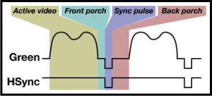
In short, you draw the pixel line by line on the screen and every line contains an active video phase in which the rgb pixels are sent and a blanking region which is divided into the front porch, sync pulse and back porch (see image below).

vga line

vga line

In the youtube tutorial its told that it starts with the blanking region followed by the active video phase. Probably it doesn’t matter but I did it in the same way (please comment if you know whats right and if it makes any difference).
It turned out that by starting with the visible area first the bending which was visible on the horizontal line is gone. I’ve updated the code accordingly.
The pixel clock and the pixel count of front porch, sync pulse, back porch and the active video phase is defined and can be seen here:
http://www-mtl.mit.edu/Courses/6.111/labkit/vga.shtml
http://tinyvga.com/vga-timing

I chose the resolution 640×480 with a pixel clock of 25.175 MHz. Let’s have a look at the code:

Our vga entity will get the pixel clock as input and outputs the horizontal and vertical sync pulse together with the rgb values (6 Bit for the MiST).
Below architecture are some constants which match the given values of our resolution. HPOS and VPOS are the horizontal and vertical counters which end positions are the sums of the above values.

With the pixel clock we change our counters. As long as HPOS is below 800 we increase it by one. If its higher we’re in the next line and set HPOS back to zero (begin of the next line). Then we check if VPOS is below 524 and if yes increase it by one and if not set it to zero (begin of the next frame).

From the figure above we see that HSYNC is only zero during the sync pulse. The same is valid for VSYNC. And thats exactly what the code above does.

The code above sets our pixels. The first section sets the rgb values to zero when we aren’t in the active video phase. Then the background is set to blue and “overdrawn” by white when the HPOS and VPOS matches certain values which will show a horizontal (HPOS) and a vertical (VPOS) white stripe in the middle of the screen.

The full source code of this example together with the Quartus project files for the MiST can be found here:
https://github.com/wsoltys/mist-cores/tree/77fea2dc1e3986daa9138dbb2fa91fd8267c3c9e/misc/vga