wsoltys in the media …

… not really but my repository at github was seen in the recent retrorgb podcast:

Looks like to totally forgot to insert a readme with the link to the original sources. Shame on me. I’ll do that later but meanwhile here the link where I got all the stuff: https://svn.pacedev.net/repos/pace/
Kudos to tcdev for all the work!

Update:
I’ve updated my repo https://github.com/wsoltys/pacedev with the latest sources from Mark’s svn and a readme to his repository.

“Retr0bright” my SNES

After watching several videos about brighten up your old retro gear I tried the method on my SNES (see 8-Bit Guy cleaning an old computer). Unfortunately with mixed results.
Instead of mixing the retr0bright mixture I’ve bought cream oxide with 12% hydrogen peroxide. Since its a cream it sticks fine on the SNES case. To prevent it from drying I wrapped it in transparent polythene foil and left it a few hours in direct sunlight.

Continue reading

Using a C128 power supply for your C64

My recently bought C64 breadbox came with the power supply which looks like a shim. The DIN connector only has 4 pins. Unfortunately it was broken somehow and since it is pured in resin it couldn’t be repaired easily (at least by me).
Looking for a replacement I found a lot of places which state the original C64 power supplies as unreliable and often responsible for a broken C64. Better would be a “new” switching power supply which was handmade and barely available these days.
I also read that the C128 has a switching power supply which delivers the same Voltage (9V~ and 5V-) as needed by the C64 but with a different power connector (square). So, why not use a C128 power supply for a C64?
I got my hands on a used C128 power supply from ebay. Unfortunately it was broken too. But the C128 power supply isn’t pured in resin and can be opened easily by removing four screws. After looking a little closer and doing some measurements the fix was quite easy by replacing the fuse on the primary side (the C128 power supply uses two fuses, both slow blow: one 315mA on the primary side and one 1.4A on the secondary side (AC)).
Okay, the power supply worked again but how to replace the square connector by the DIN one for the C64? I’ve got a few male DIN connectors but fiddling with it wasn’t m first option. Why not use the power cable from the original power supply? The shim was easy to open if you use a screw driver and a little force on the small end of the box. Even the plastic pins in the resin came out easily. Below a picture of the open C64 power supply with the DIN power cord already desoldered:

IMG_0315

Continue reading

C64 and Amiga repair and reference book in German

There’s a nice C64 and Amiga compendium free available but only in German.
It’s written by Peter Sieg and he offers the complete book as pdf and odt under the Creative Commons license.

Find the book and all files (firmware, layouts, etc.) under the link below:
Commodore-Hardware-Retrocomputing. 25 Jahre nach C64 & Co.: C64 und A500 reparieren, warten und erweitern

Direct link to the github repository:
https://github.com/petersieg/Retro-Computing

fixing a C64 with “out of memory error in 0”

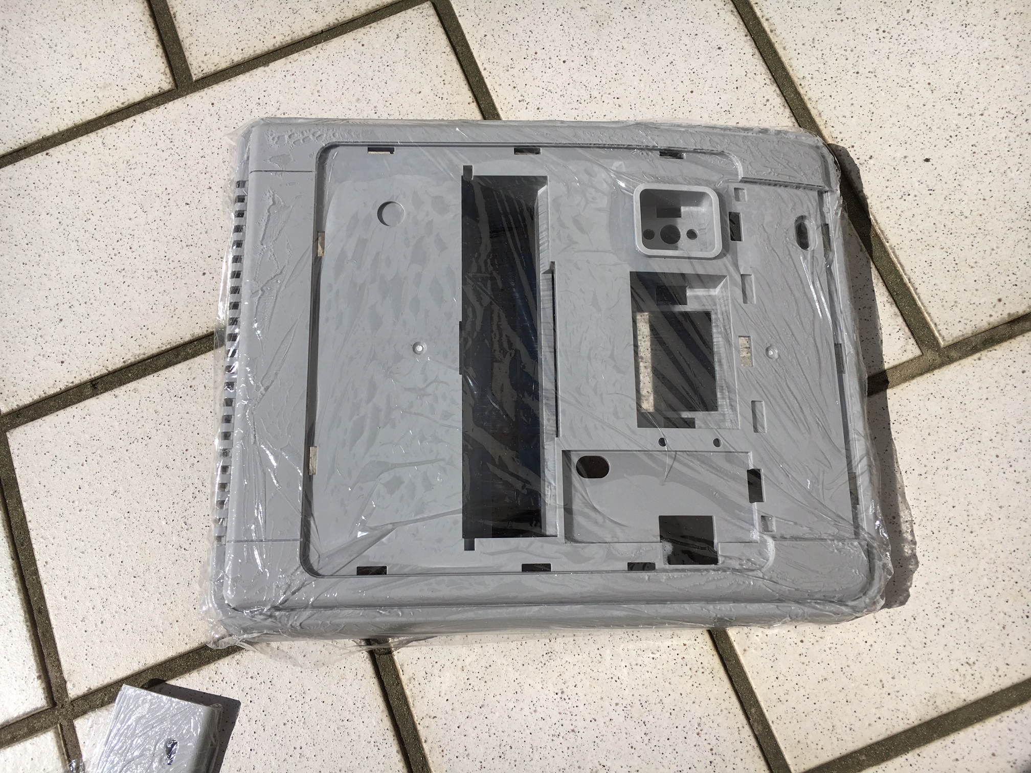
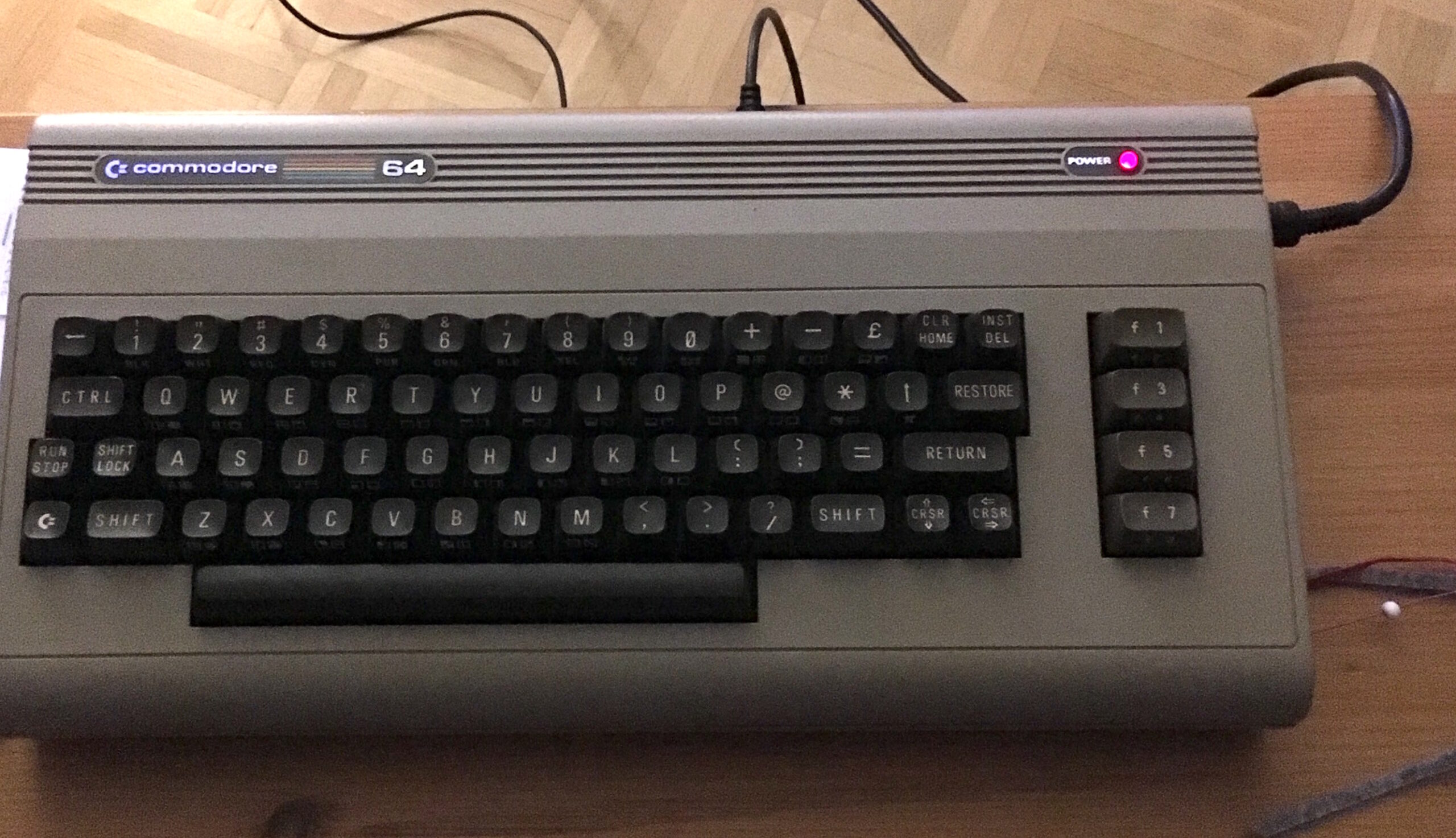
I was in the mood of messing with real hardware beside all the fpga stuff. Since I’m interested in retro hardware I bought a C64 breadbox from ebay.

The shell was pretty okay but unfortunately all that I could see on the screen was the message “out of memory error in 0”.
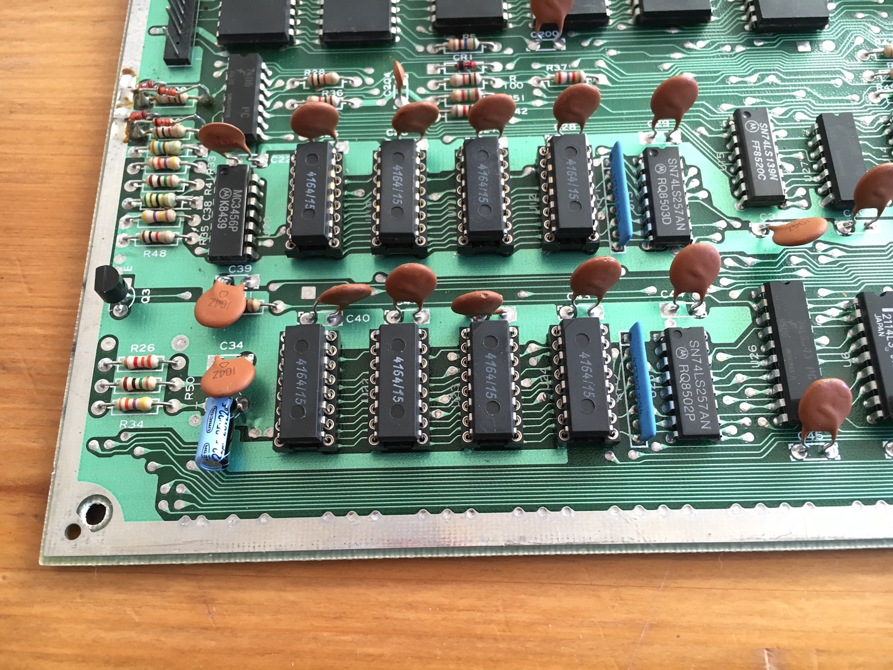
Fortunately that seems to be a common problem and the web is full of repair tips. The DRAM seems to be at fault and after 30 years it might make sense to replace it.

IMG_0298

The best is to replace all chips but there are quite a few tips on how to detect which chip might be broken. If you see random characters on the screen you might determine which bit isn’t okay and which chip is responsible for it.
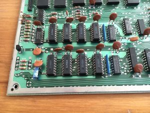
The output of my C64 was fine and all I could see was the error message. I decided to replace all eight RAM chips and put the new ones in precision IC sockets. This way I could easily swap them if necessary.

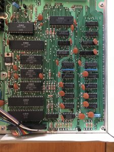
Now its time to get the solder iron and the desoldering pump to remove the solder and the chips. But that wasn’t so easy as I thought. I first added solder again to reflow the solder and then removed it with the pump. Even though it looks like I was able to remove a lot of solder I couldn’t remove the chips. The main problem were the connections vcc and ground. The circuit paths are so thick that they suck away all the heat.
As I didn’t want to keep the RAM chips I cut through all pins with a side cutter. Afterwards it was easy to remove most pins from the board but still the vcc and ground pins gave me problems. I heated it up for seconds which isn’t good as all capacitors in the near went really hot. Fortunately the ceramic capacitors could take a lot of heat and thus they still worked afterwards.

Soldering the IC sockets was easy. Afterwards I put in the new DRAM chips which I got from ebay. And guess what. My “new” C64 worked on the first try! 🙂

IMG_0299